Power Storage Unit


Engenya provided design support and guidance as an integral part of the client’s design team in the development of multiple generations of an 11 metric ton mobile chemical battery structure. This battery will form part of a renewable energy generation system.
Static, dynamic, transient and fluid-structure interaction (FSI) simulations were used to evaluate system designs against structural integrity requirements in loading situations such as road transport, rail shunt, normal operation and handling loads. Response to rail shunt was evaluated using a transient impact analysis in the time domain, while road transport loading and resulting fatigue damage were assessed using a random response analysis in the frequency domain. The risk of flow induced vibration during startup and operation was assessed with a coupled FSI model (described here).
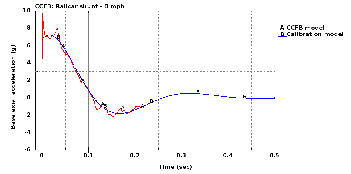
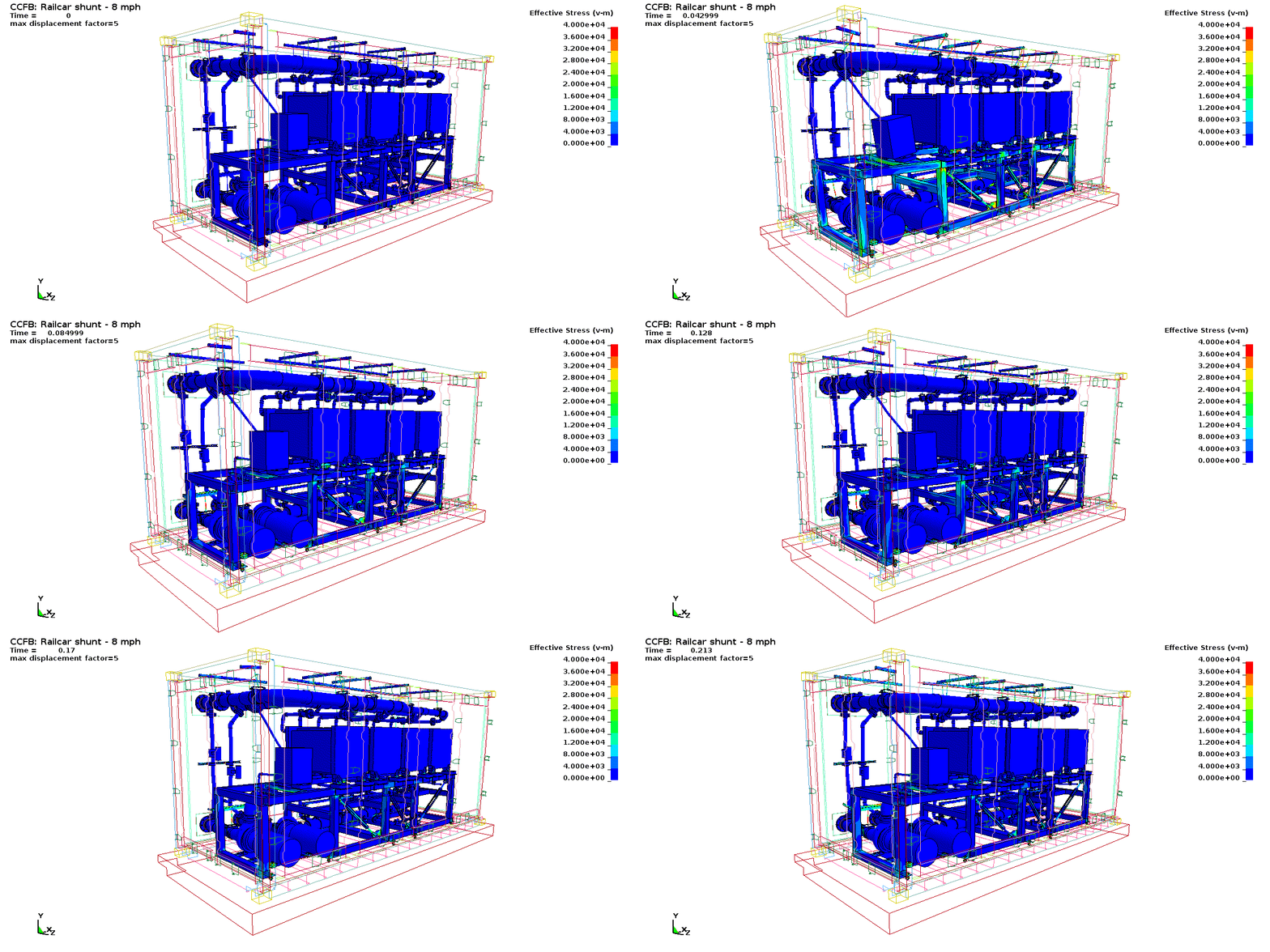
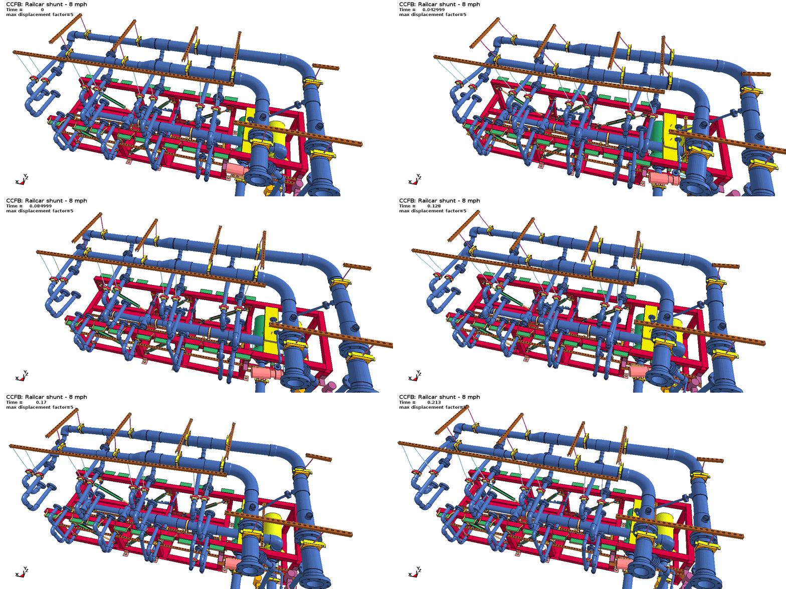
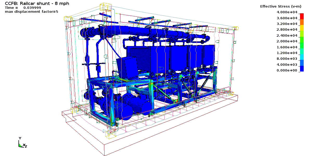
The accompanying figures depict different aspects of the railcar shunt simulation. The system is required to survive an 8 mph impact during normal shunting operations without any damage. This simulation was conducted by placing the detailed FE structural model of the system on a sliding platform representing the railcar bed, mass and shock absorbing structure, and simulating an impact against a rigid boundary from an initial velocity of 8 mph. To ensure realistic loads, the shock absorbing assembly was first calibrated against deceleration data obtained in literature for typical railcars.
Kinematic animations showing the structural displacement and stress provide an instantaneous picture of potential problem spots during the shunting impact. For example, the original design did not have cross bracing on the main frame and this was found to be a potential risk to structural integrity under the modeled loading condition. The addition of the cross-bracing shown in the animations alleviated the problem.
Other areas on which we intervened included the chemical cell mounting structures, some of the tubing support structure, and the fastening method for bolted connections.
Lockheed Martin currently markets this under the GridStar trademark.

